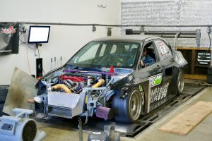
In the high-stakes world of motorsports, every fraction of a second matters — and so does every degree of engine temperature. Through clever engineering and rigourous testing, teams ensure the cooling system can keep up with the demands of a race. This article explores how teams optimise the radiator and overall cooling setup for track conditions: from sizing cores and fin-counts, to ducting, ambient adaptation, and materials. Plus you’ll find tables and lists to summarise key considerations.
If you’re shopping for components, please check out this link: Buy Radiator & Components online.
Why Radiator Optimisation Matters on Track

On race tracks, engines are pushed far beyond typical road usage: high RPMs, sustained load, rapid laps, repeated braking and acceleration, and often elevated ambient or tyre-bay temperatures. These conditions challenge the cooling system in several ways:
-
Increased heat load: More power = more heat to reject. Research shows custom radiator cores with larger volume yield better heat rejection under race loads.
-
Restricted airflow: Aerodynamics minimise drag and may reduce frontal openings or vary ducting. Some coolant systems suffer reduced airflow through the radiator.
-
Heat soak and hot-lap conditions: Successive laps raise under-hood and coolant temperatures; without effective cooling, performance drops or failures occur.
-
Ambient & track variation: Temperature, humidity, altitude and track layout affect cooling. Although less directly studied, teams must adjust accordingly.
Thus, optimising the radiator and its ancillary systems (ducting, fans, materials) becomes a performance as well as reliability exercise.
Key Parameters Teams Focus On
Below is a table summarising the main parameters motorsport cooling engineers monitor and tweak.
| Parameter | Why It Matters on Track | Typical Motorsport Adjustments |
|---|---|---|
| Core size (area & volume) | More size = more capacity to absorb and reject heat. Smaller cores may saturate under repeated laps. | Larger/double-pass cores; higher flow rate designs. |
| Fin density / fins-per-inch (FPI) | High FPI increases surface area, but also increases air-flow resistance; trade-off depending on speed and ducting. | On high speed tracks use higher FPI; on low-speed use lower FPI to reduce impedance. |
| Airflow & ducting | Without proper air through the radiator, even the best core fails. Ducting, shrouds and mounting angle matter. | Adjustable mounting brackets; tight seals; optimised angle. |
| Coolant flow rate & pump speed | Heat rejection is not just core size, but how much coolant moves; flow too slow = hotspots; too fast = insufficient heat pickup. | Optimise water pump pulley, restrictors, etc. |
| Material & construction | High strength, lightweight materials improve packaging and reliability under vibration / race use. | All-aluminium TIG-welded tanks; thick walls; pressure test rated. |
| Track condition / ambient adaptation | Changes in ambient temperature, speed, loading, altitude all shift cooling requirement. Custom setups account for worst case. | Variable ducting or insert panels, adjustable shutters. |
Typical Strategies Used by Racing Teams
Here are the common methods applied in practice:
-
Ducting optimisation & mounting angle
According to a racing-engine blog: adjusting the mounting angle of the radiator (e.g., ~7° forward tilt) improved surface-area exposure and even added front downforce while improving cooling.
Teams seal the radiator duct sides and optimise the transition shape so air flows efficiently through the core rather than bypassing. -
Fin vs flow trade-off
In short oval or low-speed tracks where airflow is restricted, a lower fins-per-inch radiator may do better because it allows more air to pass. On high-speed tracks where airflow is plentiful, a higher FPI core gives more heat rejection. -
Custom core sizing
One study on a racing car reported that increasing the core area and volume improved performance across engine speeds and load conditions.
Teams will often test multiple core designs via CFD or track testing to find the optimal trade-off between size, weight, and drag. -
Cooling system pressure & expansion design
In racing, pressurised cooling systems with proper accumulator air-space reduce coolant loss and maintain pressure under high load. A citation noted improvements in “air spring” in the circuit design. -
Ambient & track simulation
Teams prepare for worst-case ambient conditions (high temp, low airflow) by running simulations or test sessions to ensure the radiator holds up under sustained load. For example, for turbocharged engines the challenge of heat soak and intake temperature rise is significant.
When to Adjust for Specific Track Conditions
| Scenario | Cooling System Adjustment | Rationale |
|---|---|---|
| Hot ambient temperature & long straights | Use large core, maximise airflow, consider auxiliary coolers | Engine load and ambient heat both high; risk of heat-soak high. |
| Low airflow (street circuit or lots of slow corners) | Lower FPI core, add high-capacity fan, maximise ducting sealing | Because ram-air is limited, you rely more on forced airflow and lower pressure losses. |
| High downforce, tight bodywork (aero restricted openings) | Optimised ducting, variable radiator opening/shutters, minimise core face area | Aerodynamic constraints limit frontal area, so radiator design must adapt. |
| Extended endurance sessions (2-3 hours) | Oversize capacity, monitor coolant level and flow, strong pressure system | Sustained operation raises coolant temps over time; endurance needs strong margin. |
Checklist for Teams Before a Race Weekend

-
Confirm radiator core size and specification is suited to ambient & track layout
-
Inspect ducts for sealing, debris, and ensure airflow is directed through the core not around it
-
Verify fan operation, shroud sealing and ensure no bypass paths exist
-
Check coolant levels, bleed the system thoroughly (to remove air pockets)
-
Monitor temperature drop across the radiator core during testing laps to confirm heat rejection
-
Use an IR pyrometer (or thermal camera) to identify hotspots behind and around the radiator and ductwork.
-
Adjust fin density or duct boom inserts if conditions change (e.g., cooler ambient, changed track conditions)
Summary Table: Cooling Optimisation vs Performance Benefit
| Optimisation | Performance Benefit | Potential Trade-Off |
|---|---|---|
| Larger core / higher volume | Better heat rejection, more stable temps | More weight, increased frontal area or drag |
| Higher FPI core (on high-speed tracks) | Greater surface area, improved cooling | Higher pressure drop, possible airflow restriction |
| Improved ducting and mounting angle | Enhanced airflow, may contribute to aero downforce | More design complexity, may require bodywork mods |
| Adjustable openings/shutters | Tailors cooling to track/ambient, maintains aero efficiency | Adds mechanical complexity, potential failure point |
| Auxiliary coolers or dedicated loops | Manages heat soak, supports main radiator | Additional plumbing/weight, complexity |
Final Thoughts
For a race team, the radiator is much more than just a “big heat-exchanger”. It is a carefully engineered component that must interact with vehicle aero, engine thermal load, ambient conditions, packaging constraints and driver demands. Optimising it for track conditions means selecting the correct core size, fin density, ducting design, mounting geometry and integration into the overall cooling loop.
If you are building or upgrading a car for track use (whether at club level or professional), consider these motorsport-inspired strategies: think about how the air enters and exits the radiator, how the track layout influences airflow and loading, and how you’ll monitor performance over a session.
And when you’re ready to source high-quality radiators or cooling components, you can explore options here: Buy Radiator & Components online.
Optimising the cooling system doesn’t just keep things from overheating — it gives you consistent performance, reliability, and peace of mind so you can focus on speed.